
Ultrasonic weld strength depends on vibration amplitude, weld time or energy, applied force, and hold conditions. These settings work together with material properties, joint geometry, and tooling support. Increasing power alone rarely solves a weak weld because the joint must receive enough localized heating, develop adequate contact, and remain stable while the bond forms.
The practical question is which variable is limiting the joint. Insufficient melting, excessive material displacement, poor alignment, and contamination can all produce weak assemblies, but each requires a different correction. A useful adjustment starts with the failure surface and the process data, rather than an assumption that every weak joint needs more energy.
The guidance below focuses on ultrasonic welding of thermoplastics. Metal ultrasonic welding also depends on amplitude, force, and duration, but it generally forms a solid-state bond through interfacial motion and deformation. Plastic-specific advice about melting, energy directors, and cooling should not be transferred directly to metal applications.
Start with the failure, before changing the settings
Define what a strong weld must withstand in service. A housing may need resistance to separation, while a sealed assembly must also prevent leakage. A joint can pass a pull test and still leak through a small unwelded section. Conversely, a leak-tight seam may have insufficient strength for repeated mechanical loading.
Use a test that reflects the relevant load direction, such as tension, shear, peel, or torque. Keep the test setup and the interval between welding and testing consistent. Otherwise, changes in specimen temperature or loading position can obscure the effect of a parameter adjustment.
Examine where the joint fails. Clean separation along the original interface suggests limited bonding, although contamination or material incompatibility can produce similar evidence. Torn parent material can indicate a stronger interface, but it does not automatically prove an acceptable weld: excessive thinning or damage beside the seam may also cause that failure.
The machine parameters that affect ultrasonic weld strength
Vibration amplitude controls the intensity of joint heating
Amplitude describes the horn’s vibrational displacement. In thermoplastic welding, it influences cyclic deformation and frictional heating around the joint. If amplitude is too low for the material and geometry, the interface may heat too slowly or fail to develop sufficient melt.
Excessive amplitude can cause flash, surface marking, cracking, or damage to delicate features. A higher setting may shorten the weld cycle while reducing strength if it drives material out of the joint or damages the surrounding structure.
Percentage settings are not directly comparable across machines. Delivered amplitude depends on the converter, booster, horn, and generator configuration. When transferring a process, compare the physical amplitude at the horn and the tooling arrangement, rather than copying a percentage from the control screen.
Weld time, energy, and collapse determine when vibration stops
Weld time sets how long ultrasonic vibration is applied. Too little time can leave an incomplete interface; too much can create excessive melt displacement or thermal damage. Time control can work well when incoming parts and contact conditions are consistent, but it does not compensate directly for variations in how quickly the joint heats.
Energy control ends the weld after the machine records a target energy input. It can accommodate some changes in heating rate, but recorded energy is not a direct measurement of useful heat at the interface. Energy also goes into deforming the assembly and other losses. A poorly supported part can reach its energy target without producing a satisfactory bond.
Collapse control stops vibration after a specified displacement from a defined reference point. It can be useful when melting and compression of an energy director correspond closely to joint formation. Its reliability depends on stable fixturing, repeatable triggering, and limited flexing elsewhere in the assembly.
Select the primary endpoint according to the joint’s behavior, then use secondary limits to detect abnormal cycles. For example, an energy-controlled weld that suddenly takes much longer may indicate changed material condition, contact, or tooling. Passing the energy target alone should not make that cycle acceptable.
Weld force and trigger force have different jobs
Weld force maintains contact during vibration and influences how softened material flows. Insufficient force can allow unstable contact and inconsistent energy transfer. Excessive force can deform the part, suppress useful interfacial motion, or squeeze molten polymer away from the bonding area.
Force therefore has to be evaluated together with amplitude. Raising amplitude while keeping an unsuitable force setting may increase damage without correcting the underlying contact problem.
Trigger force is the contact-force threshold that starts vibration. An inconsistent trigger condition can change the starting position and the initial loading of the joint. This matters particularly when the process uses collapse distance as its endpoint.
Actuator pressure and force at the joint are different quantities. Cylinder dimensions, friction, machine mechanics, and contact area affect the relationship. Compare processes using measured or calibrated force where possible, rather than assuming that identical air-pressure settings produce identical weld conditions.
Hold time and hold force stabilize the cooling joint
After vibration stops, the joint remains hot. Hold time allows the molten region to solidify while the parts stay in position. Releasing the assembly too early can permit separation, springback, or movement that weakens the bond.
Hold force may be adjustable independently of weld force. It should maintain contact without creating unacceptable deformation or continuing to displace excessive material. Longer holding does not repair an interface that never bonded properly, so treat it as a cooling and stabilization parameter.
Material and joint design set the limits of parameter adjustment
Thermoplastic compatibility is a starting condition. Two components that look similar may contain different polymer grades, fillers, pigments, or additives. These differences can affect acoustic transmission, softening behavior, melt flow, and bonding. Machine adjustments cannot reliably overcome a fundamentally incompatible material pair.
Moisture also matters for moisture-sensitive polymers. During processing, it can contribute to voids, degradation, and inconsistent weld behavior. Control drying and storage according to the resin’s requirements, including exposure between drying and assembly. Oil, mold release, dust, and other contamination can interfere with intimate contact at the interface.
Amorphous and semicrystalline polymers often respond differently during welding because their softening and melting behavior differs. Filled grades may change stiffness and vibration transmission while reducing the amount of polymer available at the interface. A recipe established for one grade should therefore be re-evaluated when the formulation changes.
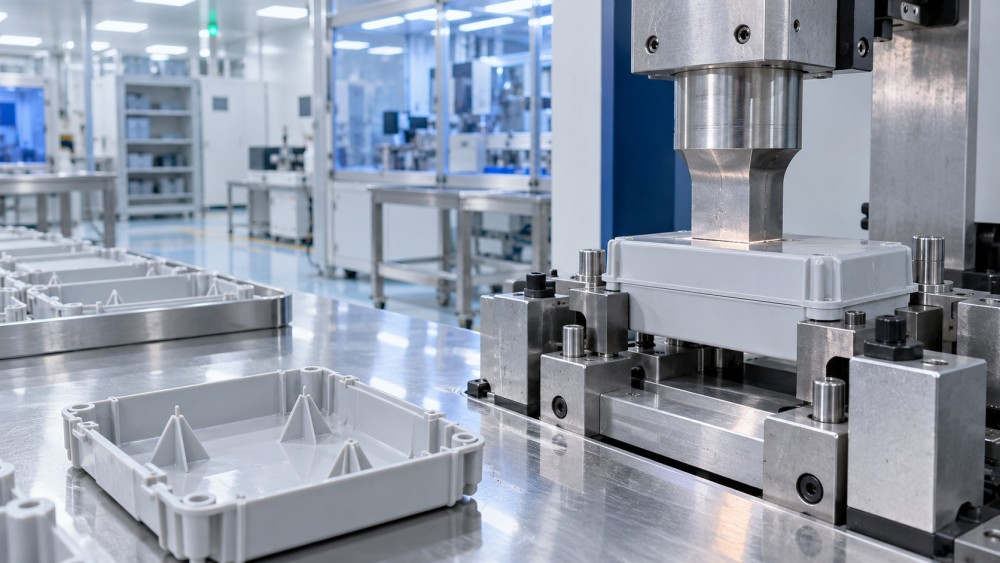
Joint geometry determines where heating begins and how the melt develops. An energy director is a molded feature that concentrates initial contact and deformation into a small region. Its height, angle, continuity, and location affect the onset of melting and the resulting bond area.
If the feature varies between molded parts, identical machine settings can produce different results. An undersized or damaged energy director may not generate enough localized heating. An oversized feature can require excessive collapse or leave unwanted flash. Shear joints and other designs have different fit and support requirements; an energy-director recipe is not automatically transferable.
Check the load path through the finished joint as well. Increasing welded area may improve capacity, but a larger seam is useful only if it welds consistently and carries the applied load effectively. Corners, abrupt wall changes, and peel loading can concentrate stress in a small section of an otherwise acceptable weld.
Tooling and frequency determine how vibration reaches the seam
The horn must deliver suitable vibration across its working face, while the fixture supports the assembly without unwanted movement. Misalignment can overload one side of the joint and leave the opposite side incompletely welded. This may appear as uneven flash, unequal collapse, or a leak at a repeatable location.
A flexible wall or unsupported span can absorb motion that should reach the seam. It may also bend enough to satisfy a displacement target before the interface has formed correctly. Check horn contact, fixture seating, part orientation, and support beneath the joint before increasing energy.
Equipment frequency is usually selected as part of the machine and tooling configuration. It affects the available tooling and amplitude characteristics, so it deserves attention when choosing equipment or transferring an application. It is generally not a routine adjustment on an installed system. Neither frequency nor generator power rating establishes weld strength by itself; the system must deliver controlled vibration to the actual assembly.
Use the symptoms to narrow the next adjustment
Several causes can produce the same visible defect. The following checks help prioritize investigation without treating appearance as proof of a specific cause.
Build a repeatable process window
A usable process window is a range of conditions that consistently meets the application’s requirements. One strong sample at a single setting gives little evidence that the process will tolerate normal production variation.
- Set measurable acceptance criteria. Include the relevant strength test, leakage requirement, dimensions, appearance, and limits on surrounding damage.
- Stabilize the inputs. Use controlled material condition, consistent molded parts, clean interfaces, and repeatable fixture seating.
- Establish a conservative starting recipe. Base it on the material, joint design, and tooling configuration. Record the endpoint mode, amplitude, force, trigger, and hold conditions.
- Adjust with a defined purpose. Begin with small changes that address the observed failure. Record both test results and process traces so the effect remains interpretable.
- Evaluate interactions. Once the joint forms consistently, use a structured experiment to examine combinations such as amplitude and force. Changing one factor at a time can miss these relationships.
- Challenge the acceptable range. Include representative part variation and the operating conditions expected in production. Choose a setting with margin from weak bonding and excessive damage.
Track weld energy, duration, peak power, displacement, and force where the equipment supports them. These signals help identify drift, but they remain indirect indicators of bond quality. Establish their relationship to physical testing before using them as production acceptance limits.
If stable incoming parts and sound tooling still produce a narrow or inconsistent process window, revisit the joint design or equipment fit. Repeatedly adding energy may hide the limitation temporarily. The next useful action is to identify whether the assembly needs better support, a different contact geometry, or a system capable of delivering the required vibration consistently.