
Plastic Welding Technology for Electronics: Choosing Methods for Housings and Sensors
Selecting plastic welding technology for electronics is rarely a simple question of machine cost or cycle time. The joint may be the barrier that keeps moisture away from a sensor element, the mechanical structure protecting a printed circuit board, or the visible seam that determines whether a finished control unit looks acceptable to an OEM. A weld that appears sound immediately after assembly can still fail later because of internal stress, poor material compatibility, particulate generation, or an incomplete sealing path.
For technical evaluators, the central task is to match the welding process to the component’s real operating conditions. Ultrasonic, laser, hot-plate, and vibration welding can all produce robust plastic assemblies, but they place heat, pressure, and vibration into the part in very different ways. Electronics housings and sensor assemblies are especially sensitive to those differences because they often combine thin walls, cosmetic exterior surfaces, embedded metal contacts, transparent windows, membranes, potting compounds, and delicate internal components.
The best decision usually starts before a supplier comparison. It starts with the joint design, polymer choice, sealing target, and assembly sequence. In plastic welding technology for electronics, equipment capability matters, but part geometry and process control usually decide whether that capability can be used reliably.
Define what the weld must protect
An electronics enclosure may need more than mechanical attachment. It may need to prevent water ingress, resist cleaning agents, retain pressure, limit electromagnetic leakage, or prevent tampering. A compact sensor may require a continuous perimeter seal while also keeping the active sensing zone free from deformation. These are different engineering problems, even when the housings look similar.
Before choosing a method, clarify whether the joint is structural, environmental, cosmetic, or all three. A snap fit plus a local weld can be adequate for an indoor consumer device. A housing exposed to outdoor temperature cycling, vibration, fluid splashes, or washdown conditions may need a controlled hermetic-like or water-resistant sealing strategy, subject to the project’s actual test requirements. The applicable ingress, chemical-resistance, electrical-safety, or product-specific requirements should be confirmed early rather than inferred from the welding method alone.
Internal clearance deserves equal attention. Even if the weld interface is remote from the PCB, vibration or downward collapse at the perimeter can transfer load through ribs, clips, terminals, or locator pins. A process that is safe for an empty housing is not automatically safe once a populated board, battery cell, display, or calibrated sensor is installed.
How the main welding methods behave in electronic assemblies
Ultrasonic welding uses high-frequency mechanical vibration to create localized heat at the joint interface. It is often considered for smaller housings, clips, filter frames, battery-related plastic components, and sensor covers because weld times can be short and no adhesive curing stage is required. The process works particularly well when the joint is designed with an energy director, shear feature, or other intentional melt zone. Its limitation is equally important: vibration and concentrated stress can be problematic near fragile internal electronics, very thin cosmetic walls, loose inserts, or highly sensitive sensor elements.
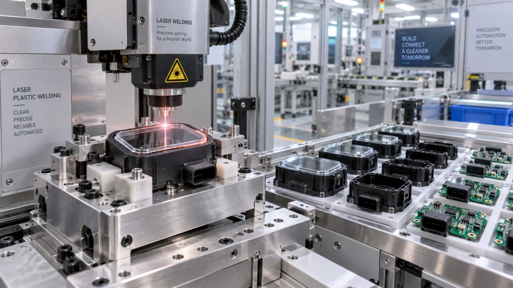
Laser welding creates heat through a focused laser beam, typically with one joining part transmitting the relevant wavelength and the mating part absorbing it. The method can offer a clean external appearance, low particle generation, and minimal mechanical vibration. It is often attractive for sealed sensor bodies, transparent-to-opaque joint configurations, medical or automotive-style electronic modules, and housings where the visible surface cannot tolerate witness marks. However, material formulation, colorants, fillers, wall thickness, and optical transmission must be validated with representative samples. A resin described simply as “laser weldable” is not enough to confirm process stability for a specific molded part.
Hot-plate welding heats the joining surfaces through contact with a temperature-controlled platen, then presses the softened surfaces together. It is suited to larger parts, irregular seams, and polymers that may not be ideal for ultrasonic joining. The approach can produce strong and broad weld areas, but the heating stage makes it less suitable when nearby electronics cannot tolerate thermal exposure or when the assembly sequence leaves little room for heated tooling. It also requires practical control of platen cleanliness, part handling, transfer distance, and melt consistency.
Vibration welding generates frictional heat through relative linear motion between parts under pressure. It is commonly considered for larger, more rigid thermoplastic housings where a broad perimeter joint is needed. It can handle some material and geometry combinations that are difficult for ultrasonic welding, but the motion requires clearance and robust fixturing. For compact electronics, the movement can be incompatible with pre-installed boards, lenses, connectors, or sensor structures unless the assembly is designed around the process.
Material compatibility is more specific than resin family
Technical discussions often begin with resin labels such as ABS, polypropylene, polycarbonate, nylon, or PBT. That is useful, but not sufficient. Grade-level differences can change melt behavior, moisture sensitivity, filler content, pigment response, optical transmission, dimensional stability, and weld strength. Regrind policies and mold-process variation can further affect the result.
This is particularly relevant for electronics. A flame-retardant compound, glass-filled grade, conductive formulation, or UV-stabilized black housing may meet the product’s functional needs while becoming more demanding to weld. Laser transmission through black plastics, for example, depends on the specific additive package and wavelength interaction; it should be tested rather than assumed. Filled materials may also alter the flow of molten polymer at an ultrasonic or vibration-welded interface.
Whenever possible, qualification trials should use production-intent resin, molded geometry, surface finish, and internal stack-up. Prototype parts made from a different grade or produced under different molding conditions can provide an early indication, but they may not reveal the variation that appears in production.
The joint design often determines the process window
A welding machine cannot fully compensate for a joint that has no controlled melting path or no place for displaced material to go. For ultrasonic welding, an energy director can concentrate melting at a predictable location, while a shear joint can support stronger enclosure sealing when designed with appropriate interference and collapse allowance. Laser welding benefits from controlled contact between parts because a gap can reduce heat transfer and create discontinuous fusion. Hot-plate and vibration welding also need sufficient weld land, flash management, and rigidity so that the part remains stable during joining.
A common mistake is to treat the exterior seam as the only geometric concern. Internal ribs can act as unintended heat sinks or stress paths. Tall walls may deflect under clamping force. Molded-in inserts can disturb local pressure distribution. If a sensor housing includes a vent membrane, gasket, lens, or wire exit, those features should be considered as part of the weld-system design rather than added late in the project.
For sensor products, the sequence is especially consequential. Welding before electronics installation can reduce exposure to heat and vibration, but may limit subsequent access for calibration or leak testing. Welding after final assembly can simplify containment of internal parts, but makes fixture design and parameter control more demanding. There is no universal preference; the acceptable sequence depends on what the sensor can tolerate and how failures will be detected.
Evaluate the process as a controlled system, not a single weld cycle
A credible equipment review should cover more than nominal power, frequency, or advertised speed. Ask how the machine controls force, displacement, time, energy, temperature, or welding path, depending on the technology. Ask which process values can be recorded for each assembly, how the system handles an out-of-range cycle, and whether it can distinguish a part-present issue from a genuine welding defect.
For electronics housings, collapse distance and final part height are often useful quality indicators because they reflect whether the intended melt and seating occurred. They should not be treated as proof of sealing by themselves. A weld can reach its expected collapse while still containing a local channel, contamination, incomplete contact, or material defect. Where sealing is critical, the production plan may need a complementary verification method, such as pressure-decay, vacuum-decay, flow-based testing, visual inspection, or a product-specific functional test. The appropriate method depends on the enclosure design and the failure mode being controlled.
Fixtures deserve the same scrutiny as the welder. A nest that does not support thin walls consistently can create cosmetic marks, skewed joints, or variable energy transfer. Tooling should locate from stable functional datums, avoid loading connectors and display windows, and allow sufficient access for unloading and inspection. Wear surfaces, horn or sonotrode condition, platen cleanliness, and clamping alignment need a maintenance plan. These details are easy to overlook during trials and difficult to ignore after reject rates rise.
Cleanliness and traceability belong in the selection decision
Welding cannot reliably overcome contamination at the interface. Mold-release residue, dust, machining debris, oils, moisture, or handling contamination may interfere with bonding and can become a leakage path. The required preparation may range from controlled part storage and dry handling to a defined cleaning stage. In precision applications, ultrasonic cleaning can remove fine contaminants from suitable components, but compatibility with the part, electronics, and downstream process must be assessed.
Traceability should also be designed around the assembly flow. A serial number, lot code, or two-dimensional code applied by laser marking or inkjet coding can connect the enclosure to its welding record, material lot, leak-test result, and final electrical test. Placement matters: marking a surface that later becomes hidden, stressed, coated, or exposed to abrasion may reduce readability. The traceability strategy should be reviewed alongside weld geometry and post-processing, not after the line layout is fixed.
This broader view is central to the work covered by Global General Industrial Auxiliary Systems (GIAS). Welding, cleaning, marking, vacuum testing, and surface-related processes are frequently treated as separate equipment categories. In practice, they influence the same quality outcome: whether an electronic product leaves the factory clean, sealed, identifiable, and consistent from one production lot to the next.
A practical path to a defensible choice
The most reliable selection process narrows options through evidence. Start with the production-intent CAD model and polymer specification. Identify the functional seam, internal no-go zones, allowable cosmetic marks, required output, and expected environmental exposure. Then assess whether the proposed method imposes vibration, heat, motion, or clamping loads that conflict with the installed electronic content.
Representative trials should examine more than initial pull strength. Inspect flash, witness marks, dimensional shift, internal damage, and consistency across parts. If the housing is intended to resist ingress, test the actual sealing requirement with the electronics or realistic internal mass included where relevant. Review process signatures over repeated cycles, because a wide process window is usually more valuable in production than an impressive result obtained from one carefully adjusted sample.
For many compact assemblies, ultrasonic welding remains a practical and efficient choice when the joint is designed for it and internal components are protected. Laser welding becomes compelling where appearance, low particulate generation, and low vibration outweigh material-validation effort. Hot-plate and vibration welding remain strong options for larger or more demanding enclosure geometries, provided the assembly can accommodate their heat or movement. The right answer is not the most familiar technology; it is the one that creates a stable joint while preserving the function of everything inside it.