
When Does Coating Measurement Require Destructive Testing?
Most routine coating measurement should be non-destructive. A calibrated magnetic induction gauge, eddy-current instrument, ultrasonic thickness gauge, or optical method can provide fast readings without sacrificing a finished part. That matters when the component is expensive, already assembled, or needed for shipment.
But a non-destructive thickness reading is not always a complete answer. It may confirm that material exists above a substrate, while failing to reveal whether several layers are correctly arranged, whether a conversion coating is present, whether a void sits beneath the surface, or whether a coating has actually bonded to the part. In safety-critical, highly regulated, or failure-prone applications, destructive testing is sometimes the only practical way to see what the coating system is doing.
For quality and safety teams, the decision is rarely “destructive versus non-destructive” in the abstract. The real question is whether the uncertainty left by a non-destructive coating measurement creates an unacceptable product, compliance, corrosion, or service-life risk. The most effective inspection plans use both approaches: non-destructive testing for production control and destructive examination for qualification, investigation, and periodic verification.
What non-destructive coating measurement can—and cannot—confirm
Non-destructive techniques are well suited to high-volume inspection. Magnetic induction is commonly used for non-magnetic coatings on ferrous substrates; eddy-current methods are commonly used for non-conductive coatings on non-ferrous conductive metals. Ultrasonic gauges can be useful where the coating and substrate combination permits a clear acoustic response, including certain thick polymer coatings on metal, composites, or concrete.
These tools are valuable because they are quick, portable, and repeatable when the instrument, probe, substrate, surface condition, and calibration procedure are appropriate. ASTM D7091 addresses non-destructive dry-film thickness measurement of non-magnetic coatings applied to ferrous and non-ferrous metal substrates. ISO 2808 also describes a range of methods for determining film thickness. In practice, the applicable customer specification or governing standard should decide the acceptance method rather than habit alone.
Still, a gauge reading is an indirect measurement. A reading of “acceptable thickness” does not necessarily mean that every layer meets its own requirement. Consider a zinc-rich primer, intermediate epoxy, and polyurethane topcoat. A gauge may report the total dry-film thickness accurately enough, yet it cannot automatically confirm that the primer is continuous, that the intermediate coat has not been skipped in a local repair area, or that the topcoat thickness is evenly distributed over sharp edges.
That distinction becomes especially important where coating systems serve more than an appearance function. In electrostatic powder coating, liquid coating, vacuum-deposited films, protective linings, and specialty surface treatments, the thickness value may be only one piece of the quality picture. Surface cleanliness, pretreatment quality, cure condition, geometry, grounding, spray pattern, and handling after coating can all affect real-world performance.
Situations where destructive testing is justified
Destructive testing becomes reasonable when the result must answer a question that a surface gauge cannot resolve. The sample is intentionally cut, stripped, pulled, bent, scribed, or otherwise damaged. That sounds severe, but when planned correctly, the damaged item is a representative coupon, witness panel, retained sample, or statistically selected production part—not a random finished assembly pulled from inventory after packaging.
1. The coating is multilayered or includes very thin individual layers
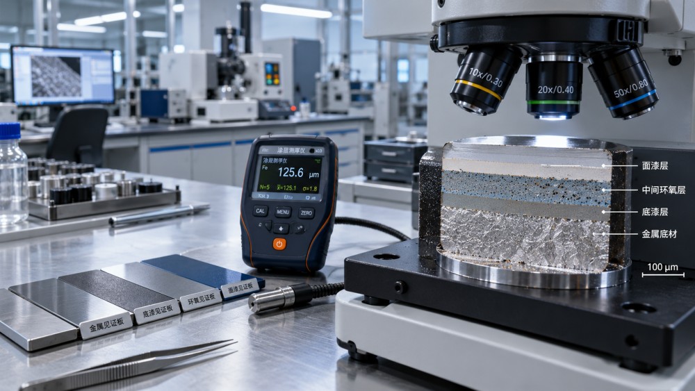
Cross-sectional microscopy is often the clearest option when each layer needs separate verification. A total thickness gauge cannot reliably distinguish between a primer that is too thin and a topcoat that is too thick if the combined build remains within tolerance. Sectioning can reveal individual layer thicknesses, intercoat boundaries, embedded contaminants, porosity, and local discontinuities.
ASTM B487 is one established method for measuring coating thickness by microscope examination of a cross section. It is commonly associated with metallic and oxide coatings, although the suitability of any cross-section method depends on the coating, preparation technique, and specification. The key point is not merely cutting the sample: poor section preparation can smear soft coatings, tear interfaces, or produce a misleading edge profile. The laboratory procedure and technician skill matter.
2. Geometry makes gauge readings unreliable
Edges, weld seams, narrow recesses, small radii, internal bores, fastener locations, and heavily profiled surfaces are common sources of false confidence. Most handheld gauges have limits related to curvature, substrate thickness, probe orientation, and measurement area. A reading taken beside a weld may not represent the coating over the weld itself. Likewise, a flat calibration plate does not fully replicate a complex casting or fabricated enclosure.
When a coating failure repeatedly begins in an inaccessible or geometrically difficult area, a section through that area may be more informative than taking another series of surface readings. This is particularly relevant to electrostatic coating, where Faraday-cage effects can reduce deposition in deep corners and recesses. A finished surface may look uniform under normal lighting while the critical recess has insufficient film build.
3. Adhesion, cohesion, or intercoat failure is suspected
Thickness alone does not predict adhesion. A coating can meet its dry-film requirement and still detach because the substrate was inadequately cleaned, the pretreatment was incomplete, moisture remained on the part, the recoat window was missed, or cure conditions were incorrect. In these situations, the inspection team needs to determine where separation occurs: at the substrate interface, between coats, or within the coating itself.
Cross-hatch adhesion testing, such as methods covered by ASTM D3359 or ISO 2409, intentionally cuts through a coating and evaluates removal after tape application. It is useful for many paint and coating systems, but it is not universally appropriate, particularly for very thick, highly elastic, or certain hard coatings. Pull-off adhesion testing, addressed in ASTM D4541 and ISO 4624, can provide a more direct tensile adhesion result, but it requires bonding a dolly and commonly leaves the test location unusable.
There is an operational lesson here: do not order a pull-off test simply because a report needs an adhesion number. Select it when the failure mode, specification, coating type, and test area justify it. A poorly selected adhesion test may damage a sound coating without resolving the actual concern.
4. A safety, corrosion, or compliance investigation requires evidence
Destructive examination is often necessary after premature corrosion, blistering, cracking, delamination, chemical attack, or contamination is found in service. The goal is no longer routine acceptance. It is root-cause analysis.
A cross section may show underfilm corrosion, incomplete surface preparation, an unexpected layer sequence, excessive edge thinning, trapped particulate, or voids associated with poor application. Depending on the material system and investigation scope, laboratories may combine sectioning with microscopy, chemical analysis, or examination of the substrate and pretreatment layer. The exact methods should be defined by competent technical personnel because sampling can either preserve or destroy valuable failure evidence.
For safety managers, this is not a laboratory-only issue. Coating breakdown on guarding, chemical containment equipment, pressure-related components, electrical enclosures, structural steel, or process equipment can create hazards well before a component visibly fails. If the coating forms part of the corrosion-control strategy, a disputed or anomalous thickness result may warrant deeper testing before the equipment returns to service.
5. The production process has changed
A destructive test is often most valuable immediately after a meaningful process change: a new powder supplier, revised pretreatment chemistry, different curing profile, new spray gun settings, altered grounding arrangement, new substrate grade, or a change in cleaning and handling. These changes may not trigger an immediate out-of-tolerance result on a handheld gauge, but they can alter adhesion, coverage, porosity, or layer consistency.
This is why witness panels are practical. A panel processed alongside production parts can be used for destructive coating measurement and adhesion tests while preserving the saleable product. The panel must genuinely experience comparable cleaning, pretreatment, coating, curing, and handling conditions. A coupon coated in a convenient location but not exposed to the same line conditions is weak evidence.
Choosing the right destructive method
“Destructive testing” is a broad label. The correct method depends on the unanswered question, not on a desire for more testing. A simple comparison helps keep the decision focused.
The method should be written into the control plan with clear acceptance criteria, sampling location, sample preparation requirements, and reporting expectations. “Test adhesion” or “check coating thickness” is not enough. It leaves too much room for inconsistent interpretation between a coating applicator, a customer inspector, and an independent laboratory.
A sensible testing strategy protects both product and evidence
The mistake is not using destructive tests; the mistake is using them reactively, without a sampling strategy. For most production environments, routine non-destructive checks should control day-to-day variation. Destructive tests should be reserved for first-article approval, process qualification, periodic audit, supplier or material changes, complaint investigation, and any condition where an NDT result conflicts with visible performance.
Before sectioning a failed component, document the condition. Photograph the affected area, record part identification, map thickness readings around the defect, note exposure history, and retain representative coating debris if relevant. Traceability is especially useful where laser marking or inkjet coding links the part to a batch, coating line, cure cycle, or inspection record. A damaged sample with no process history is far less useful than a properly documented one.
Also consider upstream controls. Coating problems are frequently rooted before the coating booth: residual oil after machining, incomplete ultrasonic cleaning, unstable rinse quality, poor masking, inadequate drying, or contamination introduced during handling. A destructive section may identify the symptom, but the corrective action may belong in cleaning, pretreatment, material handling, or process monitoring rather than in the coating operation itself.
The practical threshold: when uncertainty costs more than a sacrificed sample
Destructive coating measurement is required when the acceptance decision depends on information that cannot be credibly obtained from the surface. That usually means separate layer verification, adhesion assessment, inaccessible critical areas, failure investigation, or qualification under a demanding specification. It may also be required when the contract, customer standard, or regulated application explicitly calls for it.
For industrial quality teams, the best approach is not to treat destructive testing as a sign that the process has failed. Used on representative samples, it is a disciplined way to verify what routine gauges cannot see. In coating operations, as in cleaning, vacuum processing, batching, and identification systems, the final defect often begins with a small process variation that ordinary inspection does not immediately expose. The right test is the one that turns that uncertainty into evidence before it becomes a field failure.