
Knowing how to measure coating thickness without damaging the substrate is a practical requirement for quality control, safety, and compliance—not simply a laboratory exercise. A coating that is too thin may fail to provide corrosion resistance, electrical insulation, chemical protection, or the intended appearance. A coating that is too thick can crack, cure unevenly, interfere with assembly tolerances, or conceal a process problem that will reappear later in production.
For a quality inspector, the challenge is often more specific: the part may be expensive, safety-critical, already assembled, or intended for shipment. Cutting through the finish, removing a sample, or using a destructive cross-section method is not an acceptable first choice. The right non-destructive method makes it possible to verify dry film thickness while preserving the component and maintaining traceability.
The best technique depends on four things: the coating material, the substrate material, the coating system, and the shape of the part. A powder-coated steel bracket, an anodized aluminum housing, a polymer liner on a tank, and a multilayer plated electronic component cannot be evaluated with the same gauge or the same acceptance logic.
Begin with the coating–substrate combination
Before selecting an instrument, identify what is being measured. This sounds obvious, but many unreliable thickness readings begin with an incorrect assumption about the base material. A magnetic gauge is not “a paint gauge for everything”; it is designed for specific physical conditions.
Where the coating is on carbon steel, magnetic induction is usually the most direct field method. The probe detects the change in magnetic flux caused by the non-magnetic coating separating it from the ferrous substrate. For non-conductive coatings on aluminum or other conductive non-ferrous metals, eddy current gauges respond to changes in induced electrical currents.
Modern dual-mode instruments can often recognize whether the substrate is ferrous or non-ferrous. That convenience is useful on mixed-material production lines, but it does not replace verification. An inspector should still confirm the substrate type, especially where stainless steel grades, thin substrates, plated materials, or hidden reinforcement may affect the reading.
Magnetic induction and eddy current: the everyday inspection tools
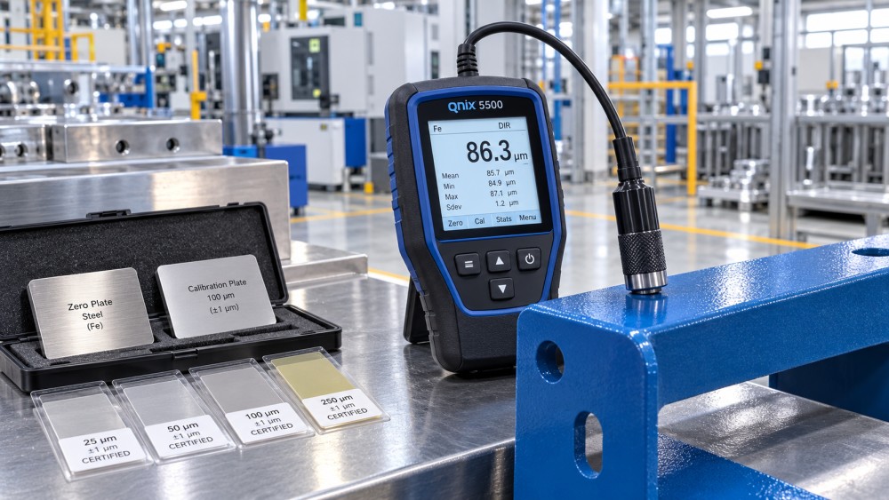
For many painted, powder-coated, or galvanized metal parts, these two methods provide the fastest answer to how to measure coating thickness without damaging the substrate. They are portable, repeatable when properly calibrated, and suitable for routine incoming inspection, in-process checks, and final release.
A magnetic induction gauge is generally used for non-magnetic coatings over magnetic substrates. Common examples include epoxy paint on structural steel, polyester powder on fabricated enclosures, and zinc coatings on steel. Eddy current measurement is used when the base is conductive but non-magnetic, such as aluminum panels with an anodized or painted finish.
Both methods are contact-based, but the contact is gentle. The probe rests on the coating surface; it does not pierce or abrade it. Still, “non-destructive” does not mean “careless.” A rough probe landing, a contaminated tip, or repeated measurement on a soft uncured coating can leave marks. On delicate decorative finishes, operators should use the probe style recommended by the instrument supplier and confirm that the coating has reached its handling cure.
Calibration is part of the measurement, not a preamble
A gauge taken directly from a drawer may produce a number, but that number is not automatically defensible. Calibration or verification should reflect the actual substrate and the expected thickness range. A smooth steel calibration plate may not represent a rough blast-cleaned component. Likewise, a flat panel does not behave exactly like a narrow tube, sharp edge, or small-radius part.
A practical routine includes checking the instrument’s zero on an uncoated sample of the same substrate whenever possible, then verifying it with certified shims or foils near the expected coating thickness. If the component has a textured powder finish or a rough protective coating, use the measurement procedure specified for that finish rather than forcing a smooth-surface expectation onto it.
International guidance such as ISO 2178 for magnetic methods and ISO 2360 for eddy current measurement can help define the method. ASTM D7091 is also widely referenced for non-destructive dry film thickness measurement using magnetic and eddy current gauges. The applicable purchase specification, customer requirement, or internal control plan should determine the final sampling and acceptance approach.
When ultrasonic measurement is the better fit
Magnetic and eddy current gauges rely on the electrical or magnetic behavior of the substrate. They are therefore not appropriate for every material combination. An ultrasonic coating thickness gauge becomes valuable when the substrate is non-metallic, when the coating is applied to a non-ferrous or non-conductive base outside the range of conventional gauges, or when a thicker protective lining must be assessed.
Ultrasonic measurement sends a sound pulse through the coating and calculates thickness from the time required for the echo to return from the coating–substrate interface. It is often used for organic coatings on plastic, composites, wood, concrete, and metals, provided there is a clear acoustic boundary and the coating system is compatible with the gauge.
This method needs more operator attention than many people expect. A small amount of couplant is normally required to transmit the sound wave. The probe must be held steadily and perpendicular to the surface. Coatings with multiple layers, internal voids, extreme roughness, or poor acoustic contrast may generate weak or misleading echoes. For multilayer systems, confirm whether the instrument reports total coating thickness or can resolve individual layers.
Ultrasonic gauges are especially useful for thicker linings used in chemical processing, storage vessels, water treatment equipment, and industrial protective systems. In these environments, a missed thin area may later become a safety event rather than merely a cosmetic defect. The measurement plan should therefore focus on high-risk zones: weld seams, corners, immersion areas, repair patches, and locations where spraying or electrostatic deposition may be less uniform.
Do not confuse a single reading with coating control
One reading in the middle of a panel rarely represents the whole part. Coating thickness changes with part geometry, grounding, spray angle, electrostatic attraction, edge effects, operator movement, and curing conditions. This is particularly relevant for electrostatic powder coating, where recessed areas and Faraday-cage regions can receive less material than open, easily accessible surfaces.
A useful inspection plan defines measurement locations before production begins. On a fabricated steel assembly, those locations may include broad flat areas, edges, weld-adjacent zones, inside corners, and areas around holes or fasteners. On a safety enclosure, inspectors may need to distinguish visible cosmetic surfaces from concealed corrosion-protection surfaces, because their specifications can differ.
Record the individual readings as well as the average where the quality system requires it. An acceptable average can hide isolated low readings that create early corrosion points. Conversely, an isolated high reading may indicate excessive powder build, poor gun distance, or a risk of interference during assembly. For protective paint systems, ISO 2808 and project-specific specifications may be used alongside agreed sampling rules; for steel structures, many organizations also use SSPC-PA 2 procedures where applicable.
Common sources of false or inconsistent readings
The instrument is only one part of the measurement system. Many apparent gauge problems are actually part-condition or technique problems.
- Curved or small parts: Curvature changes probe response. Use a suitable probe, calibrate on a similar curved substrate when possible, and follow the manufacturer’s minimum diameter guidance.
- Edges and corners: Coating commonly behaves differently at edges, while the gauge’s sensing field can extend beyond the contact point. Measure at the specified distance from an edge unless the standard explicitly requires edge coverage checks.
- Surface roughness: Blast profile, casting texture, and powder texture can create natural variation. Establish whether the requirement is nominal film build, minimum local thickness, or a value adjusted for surface profile.
- Underlying metal layers: Zinc, nickel, chrome, or other conductive layers may affect a reading depending on the method. Confirm whether the goal is total thickness or the thickness of a particular layer.
- Moisture, dust, and residue: A dirty surface can prevent stable probe contact. Clean gently without using solvents that may attack the finish.
- Uncured coatings: A coating can be thick enough but not fully cured. Thickness measurement does not replace cure, adhesion, gloss, or holiday testing.
Where XRF fits—and where it does not
X-ray fluorescence is a non-destructive option for thin metallic coatings and multilayer plating systems. It can identify elemental composition and, with the appropriate calibration and geometry, estimate individual coating layers. This makes it valuable for electroplated components, connectors, electronic parts, and decorative metal finishes where a magnetic or eddy current gauge may only provide a total response or may be unsuitable.
Its limitations are practical as well as technical. XRF equipment requires controlled operation, method validation, and radiation safety procedures. It is not the default choice for a painted steel frame or a routine powder-coating line. Use it when layer-specific metallic coating data matters and when trained personnel can manage the instrument and its compliance obligations.
A field-ready decision path for QC and safety teams
When a part arrives for inspection, avoid choosing the gauge by habit. Start by asking: Is the substrate ferrous steel, non-ferrous metal, plastic, composite, or something layered? Is the coating non-magnetic, non-conductive, metallic, or multilayer? Is the requirement for total dry film thickness, a specific layer, or minimum protection at critical points?
Then select the least invasive validated method. Magnetic induction is usually appropriate for coatings on steel; eddy current is generally appropriate for insulating coatings on aluminum and other non-ferrous conductive bases; ultrasonic testing is often the answer for thicker organic coatings and non-metal substrates; XRF is reserved for thin metallic systems where elemental layer information is needed.
Verify the gauge on a representative uncoated substrate and certified standards. Measure enough locations to reflect the part’s risk profile. Document instrument identification, calibration status, measurement locations, readings, ambient conditions when relevant, and the governing specification. This record protects more than the inspection result: it gives production, safety, and customer teams a common basis for corrective action if coating performance later comes into question.
The central lesson is simple. Non-destructive coating thickness measurement works best when it is treated as a controlled process rather than a quick number on a display. The right method preserves the substrate, supports reliable release decisions, and helps manufacturers catch the small variations that can become corrosion failures, safety concerns, or costly rework after the product has left the line.