
Start with the substrate, then assess the curve
For most routine inspections, curved parts can be measured reliably with the same non-destructive methods used on flat parts, provided the gauge, probe, calibration method, and inspection location are matched to the geometry. The first decision is still the substrate: magnetic induction gauges are generally suited to non-magnetic coatings on ferrous substrates, while eddy-current gauges are generally suited to non-conductive coatings on non-ferrous conductive substrates such as aluminium.
Curvature changes the decision because it affects how a probe sits on the surface. A reading taken from a probe that rocks, bridges a small-radius cylinder, or sits close to an edge may look precise while being systematically wrong. For technical evaluators, the question is therefore not simply which coating thickness measurement technology is available. It is whether the method can maintain controlled probe-to-surface conditions across the part’s actual inspection zones.
For curved metal components with conventional paint, powder coating, plating, or conversion-plus-topcoat systems, a dedicated magnetic induction or eddy-current instrument with a small-radius-capable probe is often the most practical choice. When the coating is thick, multilayered, inaccessible, highly textured, or applied to a non-metallic substrate, ultrasonic or cross-sectional methods may be more appropriate. No method should be selected from substrate type alone.
Why curvature creates measurement risk
Most portable coating gauges are calibrated around a predictable sensor relationship with the metal substrate. On a flat panel, the probe face makes stable contact and the instrument can interpret the signal with relatively few geometric variables. On a curved part, the field or signal path can be influenced by the radius of the component, the probe footprint, nearby edges, and local changes in wall thickness or substrate shape.
This is especially important on small tubes, shafts, fasteners, springs, castings with fillets, and formed sheet-metal components. A probe suitable for a large vessel shell may not be appropriate for a narrow pipe, even when the stated coating and substrate are identical. Convex and concave surfaces can also behave differently. The same nominal diameter does not guarantee the same response if the probe was designed primarily for outside-diameter work.
There is also a process-control issue. Coatings often become thinner around edges and tighter radii because of electrostatic effects, drainage, spray access, powder wrap, or curing behavior. If the measurement method also becomes less stable in those zones, the inspection system can miss the exact locations where coating protection is most vulnerable.
Choose the primary method by substrate and coating system
Magnetic induction for coated ferrous parts
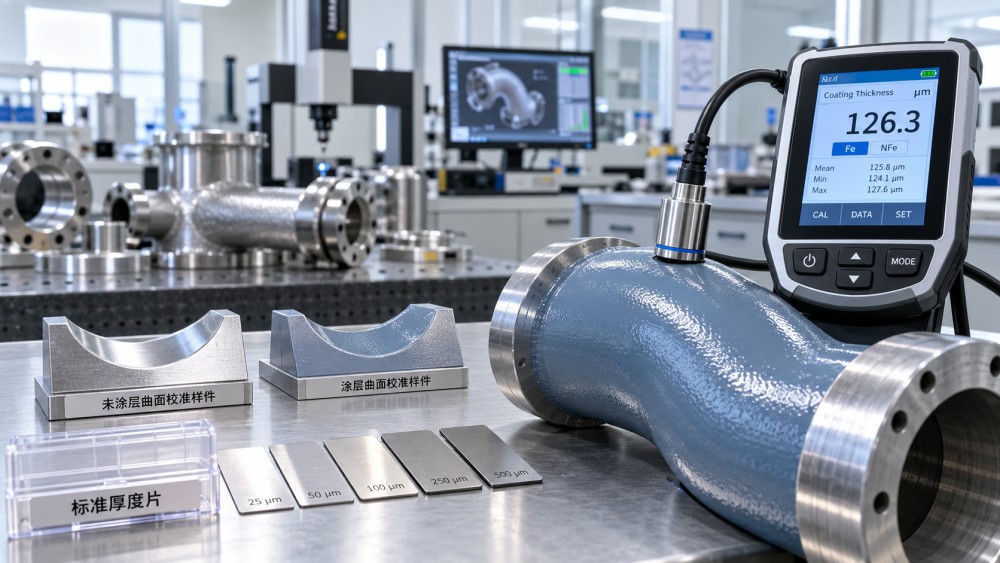
Magnetic induction is the usual first option for non-magnetic coatings over steel, iron, or other ferrous substrates. It is widely used for paint, powder coating, enamel, plastic coatings, and certain non-magnetic metallic layers on steel. For curved parts, this remains a strong choice when the instrument has a probe specified for the relevant diameter range and the calibration is performed on a matching uncoated substrate or a suitable curvature reference.
A small-tip probe can improve access to restricted features, but it does not automatically solve every curvature problem. Its contact area, allowable radius, edge clearance, and repeatability on rough surfaces should be checked in the supplier documentation and verified against representative parts. A probe that reads consistently on the crown of a tube may behave differently near a weld seam, shoulder, thread, or flange.
Eddy current for coated aluminium and other non-ferrous metals
Eddy-current measurement is commonly used for electrically non-conductive coatings over conductive non-ferrous substrates, including aluminium, copper, brass, and some stainless steels. This makes it a common method for painted aluminium housings, coated extrusions, anodized aluminium, and protective finishes on formed non-ferrous components.
The same curvature discipline applies. Thin aluminium tubing and tightly formed profiles deserve particular attention because the geometry can influence the eddy-current response. Calibration on flat shims placed over a flat reference panel may produce an acceptable-looking result that does not represent the production component. A better approach is to calibrate using uncoated production material, an uncoated part of the same shape, or a calibration standard designed for the relevant radius.
Dual-mode gauges for mixed production
Dual-mode instruments combine magnetic induction and eddy-current capability, allowing one gauge to inspect coatings on both ferrous and non-ferrous metal parts. They are useful where a quality team handles varied substrates or where component families include steel and aluminium versions. Their convenience should not be mistaken for universal suitability. The selected probe still needs to support the smallest radius, the expected thickness range, the surface condition, and the access constraints of each part.
For high-volume production, a dual-mode gauge may be an efficient platform, while dedicated probes or part-specific fixtures provide the control needed for repeatable curved-surface readings.
Ultrasonic gauges for non-metal substrates and thicker systems
Ultrasonic coating thickness measurement is often considered when the substrate is non-metallic, when individual layers need to be distinguished, or when the coating system is too thick or otherwise unsuitable for magnetic or eddy-current methods. It can be useful for coatings on plastics, composites, wood, concrete, and other non-metallic materials, subject to the material and coating combination being compatible with the instrument.
For curved surfaces, ultrasonic methods bring a different set of constraints. The probe needs adequate coupling and stable placement, and coarse textures, highly curved small parts, thin substrates, or complex multilayer structures can complicate signal interpretation. A thick coating on a large curved composite panel may be a good candidate; a narrow, sharply curved moulding may be difficult to inspect consistently. The method should be validated on the actual coating stack-up rather than assumed from a general product description.
Match the probe to the minimum radius, not the easiest surface
Technical evaluations often focus on the main body of a component because it is easy to reach and visually representative. That approach can produce a misleading inspection plan. The limiting condition is usually the tightest radius or most critical feature that must be accepted or rejected.
Before selecting a gauge, document the following features of the parts to be measured:
- Substrate material and whether its magnetic or electrical properties vary across the component.
- Coating type, expected thickness range, number of layers, and surface texture.
- Outside and inside radii, including the smallest radius that requires measurement.
- Distance from edges, holes, welds, threads, seams, and abrupt geometry changes.
- Whether the required inspection point is accessible by hand-held probe contact.
- Whether readings are needed on a visible cosmetic surface, a corrosion-critical zone, or both.
- Production volume and the required degree of repeatability between operators and shifts.
Probe specifications should be read as operating limits, not as marketing descriptors. A supplier may state that a probe is suitable for curved surfaces, but the relevant detail is the minimum diameter or radius for convex and concave geometry, along with the thickness range and stated accuracy under those conditions. If the part geometry lies near that limit, a feasibility test on production-like samples is more informative than a generic demonstration.
Calibration is part of the method, not a preliminary step
On curved parts, calibration often determines whether a conventional gauge is dependable. A field adjustment on a flat zero plate may be sufficient for a broad, gently curved surface, but it is weaker evidence for a small tube or recessed profile. The closer the measurement is to a geometric limit, the more closely the calibration standard should resemble the part.
The preferred sequence is to use an uncoated sample made from the same substrate and formed to the same geometry, then verify response with certified thickness shims or coating standards placed at the intended measurement locations. This accounts for curvature and substrate behavior together. Where an uncoated reference component is unavailable, a retained uncoated process coupon with the same material and radius is often more useful than a flat calibration plate.
Calibration should also reflect the surface condition. Rough cast steel, blasted substrate, textured powder coating, and irregular galvanizing can create reading variation that is unrelated to actual coating inconsistency. In these cases, an inspection plan should define how many readings are taken per zone and whether acceptance is based on individual readings, local averages, or a documented minimum value. A single spot reading is rarely a strong basis for judging a variable curved surface.
When a hand-held gauge is not enough
Portable gauges are efficient for incoming inspection, in-process checks, and final audit work, but some curved parts require a more controlled approach. A small precision component may need a fixture that controls probe angle and contact force. A long coated tube may need defined clock positions and axial locations so that operators inspect the same zones. A part with recessed channels may require a custom probe extension or a different inspection route altogether.
Cross-sectional microscopy remains valuable when the coating stack must be understood in detail, such as verifying individual layers, investigating poor adhesion, or resolving disagreement between non-destructive readings and functional performance. It is destructive and samples only a limited area, so it is usually a validation or failure-analysis tool rather than the routine production method.
X-ray fluorescence can be appropriate for certain metallic coating systems and applications where elemental composition and layer characteristics matter. Its suitability depends heavily on the coating/substrate combination, part access, geometry, measurement spot size, and operational controls required for the equipment. It should be considered for a defined measurement problem, not treated as a blanket upgrade for all curved components.
Optical or laser-based inspection can help map geometry or surface profile, but it does not automatically provide reliable coating thickness through opaque layers. Evaluators should separate the need to measure surface shape from the need to measure coating thickness. These are related quality questions, but they are not interchangeable.
Build the inspection plan around critical zones
The best method can still fail if readings are collected from convenient locations rather than meaningful ones. Curved parts should be divided into zones based on coating risk and process behavior. For a cylindrical part, this may include the crown, side positions, lower surface, ends, transitions, and any area affected by hanging, grounding, masking, or spray direction. For a formed housing, inspection points may be concentrated around bends, corners, recessed features, and corrosion-exposed edges.
Documenting these zones also improves traceability. When a thickness result falls outside the specification, the team can distinguish a genuine coating-process issue from a measurement condition issue. That distinction matters when corrective action may involve spray settings, part orientation, curing, masking, substrate preparation, or inspection practice.
Common selection mistakes
One frequent mistake is buying a general-purpose gauge based only on its stated accuracy. Accuracy specifications are meaningful only within the conditions used to establish them. Curvature, roughness, edge proximity, coating thickness, and operator placement can add variation beyond the headline figure.
Another is assuming that a reading is valid because it is repeatable. A probe can produce closely grouped values while consistently over-reading or under-reading on a radius outside its intended range. Repeatability must be checked alongside comparison to a suitable reference or a geometry-matched calibration condition.
A third mistake is setting one thickness requirement for the whole part without defining where it applies. Coating performance may depend on a minimum thickness at a bend or exposed edge, while cosmetic appearance may drive an upper limit on a broad visible surface. The measurement method should support those distinct requirements instead of reducing the part to one arbitrary average.
For curved parts, the most suitable coating thickness measurement method is usually the one that produces defensible readings at the actual acceptance locations, with calibration that reflects the substrate and geometry. Magnetic induction and eddy-current instruments remain the practical default for many coated metal parts. Their success depends less on the gauge category than on the right probe, representative calibration, controlled placement, and an inspection plan designed around the part’s hardest-to-measure features.