
How to Remove Contaminants from Blind Holes Without Trapping Residue
Blind-hole contaminant removal cleaning requires more than directing water or solvent at a part and assuming the cavity is clean. A blind hole has only one opening, so the same geometry that makes it useful for fastening, fluid control, alignment, or weight reduction can also trap air, oils, polishing compounds, metal fines, abrasive media, and spent cleaning chemistry.
For an operator, the difficult part is not always loosening visible soil. It is getting loosened contamination out of the hole, replacing used liquid with clean rinse water, and drying the cavity without leaving droplets or redeposited residue behind. A component can look clean under normal lighting while still carrying contamination deep in a bore. That becomes a problem later during assembly, leak testing, coating, adhesive bonding, corrosion protection, or final inspection.
The right approach depends on hole diameter, depth, orientation, material, soil type, permitted chemistry, and the cleanliness standard for the next production step. There is no universal cleaning cycle. There are, however, several practical principles that prevent the most common failure: moving contamination around inside a blind hole rather than removing it.
Why Blind Holes Behave Differently in a Cleaning Process
An open through-hole allows liquid and displaced air to move in opposite directions. In a blind hole, the incoming liquid must first overcome the air pocket at the closed end. If air remains trapped, the cleaning medium may only wet the entrance and sidewall. This is especially likely where the opening is narrow, the hole is deep, or parts enter the tank with the opening facing upward.
Once cleaning solution enters, another issue appears: the liquid has nowhere to escape freely. Metal chips, fine particulate, and emulsified oil can settle at the bottom. If the part is transferred directly from a wash tank to a rinse tank, contaminated wash solution can remain inside the cavity and dilute the rinse. A final rinse can then leave detergent salts, surfactants, or dissolved contaminants after drying.
This is why blind-hole contaminant removal cleaning should be viewed as a sequence of displacement steps: remove air, detach soil, transport soil outward, exchange dirty chemistry for clean rinse liquid, then remove liquid completely. Missing any one step can undermine the others.
Start with the Soil and the Hole Geometry
Before changing equipment settings, identify what is actually in the hole. Fresh cutting oil behaves differently from dried coolant residue. Loose machining chips may be flushed out with directed flow, while polishing compound can cling to a rough internal surface. Heat-treated scale, oxide films, adhesives, or carbonized residues may require a different chemistry or a separate pre-cleaning operation.
Geometry matters just as much. Record the hole diameter, depth, bottom shape, threads, cross-drilled passages, and whether the opening is chamfered. A narrow, deep threaded hole is harder to rinse and dry than a smooth shallow counterbore. A flat-bottom cavity can hold solids; a conical or radiused bottom may shed them more readily. If the design allows it, adding drainage relief or access for cleaning at an early engineering stage can prevent recurring production problems.
Operators should also note the material. Aluminum, carbon steel, stainless steel, copper alloys, plastics, and coated parts do not tolerate the same chemicals, temperatures, or drying conditions. Cleaning performance is never separate from material compatibility.
Use Part Orientation to Let Air Escape
Part orientation is often the first improvement to test because it does not require a new cleaning chemistry. Blind-hole openings should generally be positioned so trapped air can rise and leave the cavity during immersion. In many cases, that means angling the opening rather than pointing it straight upward. The best angle depends on the part shape and rack design, but the purpose is simple: avoid creating a sealed air pocket at the bottom of the hole.
Do not assume a basket full of parts is being cleaned uniformly. Parts touching each other can block jets, prevent liquid exchange, and shadow blind holes from ultrasonic energy. Fixtures should hold components securely while leaving openings accessible. If small parts are processed in bulk, the process needs enough movement and solution circulation to avoid packing cavities against other pieces.
A useful shop-floor check is to observe how a representative part wets during the first immersion. Persistent bubbles escaping late in the cycle, or bubbles remaining at an opening, suggest that air removal is incomplete. This visual check does not replace validation, but it can reveal a loading issue quickly.
Choose Agitation That Reaches the Bottom of the Cavity
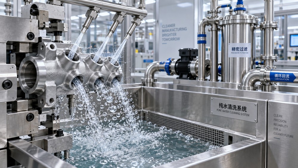
Simple soaking rarely provides enough exchange for difficult blind holes. Agitation helps cleaning liquid enter the cavity, breaks up the stagnant boundary layer near the surface, and carries loosened contamination back out. The appropriate method should match both the part and the soil.
Ultrasonic systems are frequently considered for precision parts because cavitation can help detach micron-level contaminants from recesses that brushes and spray patterns do not reach easily. But ultrasonic energy is not a substitute for liquid exchange. If the blind hole stays air-locked, cleaning action inside it will be limited. Degassing the fresh bath where appropriate, maintaining solution quality, using correct loading, and providing a suitable rinse stage are all part of the result.
Cleaning Is Not Complete Until the Rinse Is Clean
Many residue failures are actually rinse failures. The wash stage may have successfully released oil or compound, yet remnants of the wash chemistry remain in the blind hole. When the part dries, those remnants become visible deposits, cause staining, interfere with coating adhesion, or create an unexpected result in gravimetric or particle testing.
A rinse must displace the cleaning solution inside the cavity. That may require more than one rinse stage, fresh-water replenishment, agitation, or a dedicated directed rinse for critical holes. Counterflow rinsing can help preserve rinse quality in a multi-stage system, but its suitability should be reviewed against the process requirement and wastewater arrangement.
Operators should be cautious about extending wash time when the real issue is poor rinse exchange. Longer exposure can consume time and chemistry without addressing trapped liquid. A better investigation is to separate the questions: Is soil still present after washing? Is wash solution remaining after rinsing? Or is rinse water remaining after drying? Each fault needs a different correction.
Drying Must Empty the Hole, Not Seal Residue Inside It
Blind holes often retain the final droplet. Heated air may dry the outer surface first while liquid remains at the bottom of the cavity. As that liquid evaporates, it concentrates anything dissolved in it. A clean part can therefore develop a ring, crystalline deposit, discoloration, or corrosion-related issue after it leaves the washer.
Effective drying combines drainage with controlled removal of retained moisture. Depending on the component and production line, this can include reorienting or rotating the fixture, air knives, filtered blow-off, warm-air circulation, centrifugal drying for suitable small parts, or vacuum drying. Vacuum systems are particularly relevant where geometry makes liquid retention difficult to avoid, because reduced pressure can assist removal of moisture from cavities. The correct choice depends on the material, required dryness, cycle time, and the risk of moving droplets from one part to another.
Do not use excessive air pressure as a blanket solution. It may atomize contaminated liquid, push it onto other surfaces, or create handling and safety concerns. Where compressed air is used, its filtration and oil-control condition matter. Blowing a cavity with contaminated plant air defeats the cleaning operation.
Common Mistakes That Keep Residue in Blind Holes
- Loading parts with blind openings facing upward, allowing an air pocket to remain trapped.
- Using a strong wash stage followed by a weak or stagnant rinse stage.
- Treating bath concentration, temperature, contamination load, and filtration as unrelated variables.
- Cleaning mixed part families on one fixture without checking whether each cavity is exposed to flow and drainage.
- Inspecting only external surfaces because internal access is inconvenient.
- Changing several settings at once, making it impossible to identify what actually solved—or caused—the problem.
Verify the Actual Risk, Not Just the Appearance
Visual inspection can identify chips, stains, and obvious residue, but it is not enough for every component. The verification method should reflect the downstream risk. A part that will be painted may need a different cleanliness check than a hydraulic component, a medical-device component, or an electronic enclosure. Internal-cavity inspection can involve borescopes, controlled extraction and particle analysis, rinse sampling, weight-based methods, or process-specific tests. The selected method should be defined by the applicable product requirement rather than by convenience.
For production control, it is often useful to retain representative parts at different stages: after machining, after washing, after rinsing, and after drying. This makes it easier to determine where contamination is being introduced or retained. If a failure appears only after a coating or assembly process, traceability of cleaning batches, bath maintenance, loading arrangement, and drying conditions can narrow the investigation.
GIAS covers cleaning precision alongside vacuum, surface treatment, marking, batching, and other process-support technologies because these operations are connected in real factories. A blind-hole cleaning issue may first show up as a coating defect, an assembly fault, a blocked fluid path, or an inspection rejection. Looking at the entire process chain is usually more productive than blaming the wash tank alone.
Build a Repeatable Process Rather Than Relying on Extra Time
A robust process for blind holes usually comes from controlled loading, suitable chemistry, purposeful agitation, clean rinsing, and verified drying. Start with a representative difficult part rather than an easy sample. Define the cavity that creates the greatest risk, establish an acceptable inspection method, and document the fixture orientation and sequence that works. Then change one variable at a time when troubleshooting.
Before specifying new equipment or modifying an existing line, confirm the hole geometry, soil type, material limits, production volume, cleanliness requirement, water and chemical constraints, and whether the process must support coating, assembly, or regulated end use. Those details determine whether the answer is better fixturing, a revised rinse strategy, ultrasonic assistance, vacuum-supported drying, or a combination of methods. The aim is not simply a cleaner-looking hole; it is a cavity that is demonstrably free of trapped contaminants and process residue when the part reaches its next operation.