
Select a vacuum level gauge from the process window outward, not from the pump nameplate or the lowest pressure printed in a catalog. The gauge must measure the pressure range where control decisions are made, remain reliable in the actual gas environment, and reveal a meaningful change early enough to separate a process deviation from a developing leak. A sensor that reaches the required ultimate vacuum but is blind, unstable, or slow around the normal operating setpoint creates false confidence.
Start by defining three pressure conditions: the pressure at which the chamber begins useful work, the normal controlled pressure or pressure trajectory, and the highest pressure that indicates a fault. These conditions often sit far apart. A coating chamber may be evacuated from atmosphere, stabilize at an intermediate pressure, then run a deposition cycle at much lower pressure. Freeze-drying and vacuum drying may require close control through a changing vapor load. Leak testing can involve a short evacuation period followed by a pressure-rise observation. One gauge rarely provides equally useful information across all of these stages.
Map the pressure range in absolute units
Vacuum specifications become confusing when absolute pressure, gauge pressure, and percent vacuum appear in the same discussion. Sensor selection should be based on absolute pressure, because process gas density and molecular flow behavior are tied to absolute pressure. Gauge pressure measures the difference from local atmospheric pressure; it is useful for some rough vacuum duties but becomes misleading when weather, altitude, or atmospheric reference drift matters.
Write the required operating band using one unit system, then preserve it through the specification, PLC scaling, alarm settings, and acceptance test. Pascals, millibars, torr, and microns are all used in vacuum work. Conversion errors are especially damaging at low pressure, where a misplaced decimal or an assumed unit can turn a process threshold into an alarm that never activates.
Do not specify only “high vacuum” or “deep vacuum.” Define the lowest expected pressure, the normal regulation region, the upper pressure during loading or gas admission, and the pressure at which leak investigation should start. The useful measurement span is usually narrower than the total evacuation path. A gauge chosen for its wide span can have insufficient resolution or poor repeatability at the actual control point.
Match the sensing principle to the gas and pressure regime
Different gauge technologies do not measure vacuum in the same way. Their readings can react differently to gas composition, contamination, orientation, and thermal conditions. The sensor principle therefore matters as much as the stated range.
A capacitance diaphragm gauge is often the reference choice when the decision depends on actual pressure rather than gas identity. Its deflection-based measurement is much less sensitive to molecular composition than a thermal gauge. That distinction matters in degassing, drying, resin processing, vacuum packaging, and chambers where vapor concentration changes throughout a cycle.
A Pirani gauge remains useful when its limitations are understood. During evacuation of a dry air-filled chamber, its signal often tracks pump-down well. If the same chamber later receives nitrogen, helium, forming gas, or vapor from a heated product, the displayed value may no longer represent the same absolute pressure. Treating that shift as a leak can lead to unnecessary maintenance; ignoring it can hide a real control problem. Where this ambiguity exists, pair thermal measurement with a gas-independent reference or use a hybrid gauge whose control logic clearly identifies the active measurement regime.
Separate control accuracy from leak-detection sensitivity
Accuracy is commonly stated as a percentage of reading, a percentage of full scale, or a combination of both. These claims are not interchangeable. A full-scale error specification becomes less useful when a narrow operating pressure lies near the bottom of a large range. For a process threshold, calculate the permitted absolute error at the actual setpoint and compare it with the control tolerance. Also review repeatability, zero stability, temperature coefficient, and response time. A gauge can be accurate after calibration yet generate a noisy or drifting live signal that makes tight alarm limits impractical.
Leak detection imposes a different requirement. The question is not merely whether the gauge reads the final vacuum level; it is whether it resolves the pressure behavior that distinguishes a leak from normal outgassing, vapor evolution, or a changing pump load. A slow sensor can smooth out a short pressure excursion. Excessive signal filtering in the transmitter or control system can do the same. Conversely, a very fast signal without appropriate process interpretation can turn valve movement and product desorption into nuisance alarms.
For pressure-rise testing, isolate the test volume after evacuation and observe the rate of pressure increase over a defined interval. The gauge range, chamber volume, product condition, temperature, and stabilization time all affect the result. A rising pressure curve immediately after isolation may be dominated by water vapor desorbing from surfaces rather than an external leak. If the slope declines as the chamber settles, outgassing is a plausible cause. A more persistent, repeatable rise after equivalent conditioning deserves closer leak investigation. The gauge should be mounted so that it sees the isolated test volume rather than a section separated by a restrictive line, filter, valve, or cold trap.
Read the installation as part of the measurement system
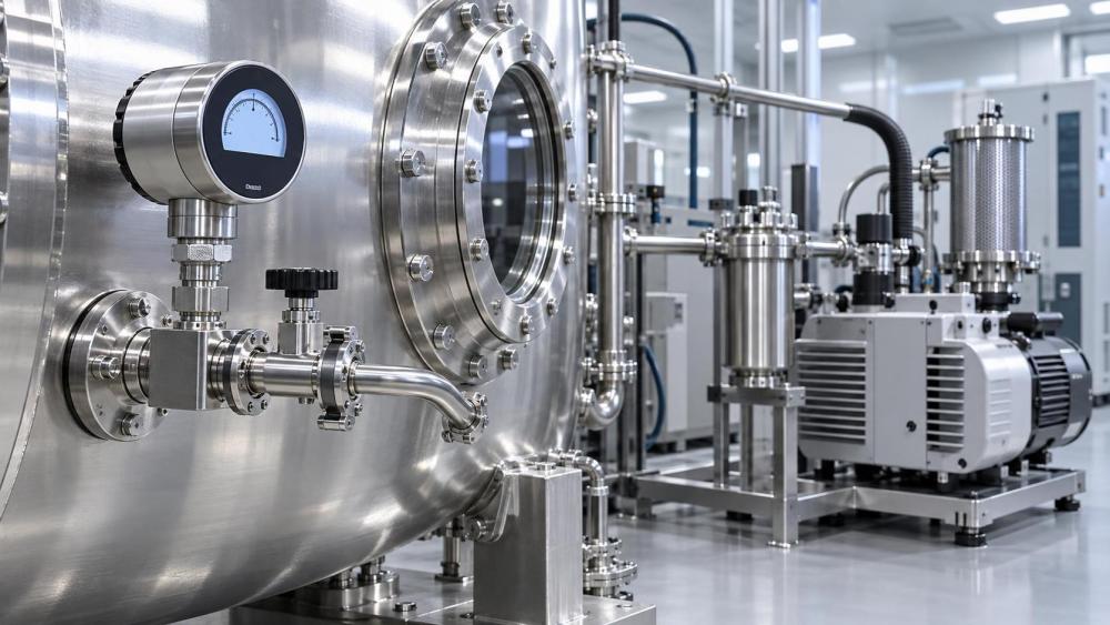
The displayed vacuum exists at the gauge port, not automatically at the work zone. Long small-diameter tubing, elbows, clogged sintered filters, and partially closed isolation valves create conductance limits. During pump-down or gas flow, pressure at the sensor can differ materially from pressure in the chamber. This is most pronounced at lower pressures, where molecular flow dominates and line geometry matters more than intuition suggests.
Place the measurement port near the chamber or critical process zone when control quality is the priority. Keep the connecting path short and clean, with a bore that does not become the governing restriction. A port directly in the path of particulate, condensable vapor, droplets, or product debris creates another problem: the instrument is close to the process but no longer measures reliably. A protected side port, a heated connection, a suitable trap, or a purge arrangement may be justified, provided its pressure drop and response effect are evaluated.
Orientation is not cosmetic. Condensate can collect against a sensing element, and a vertically mounted line can become a liquid trap. In vacuum drying or solvent-bearing processes, locate the gauge and plumbing so that liquid cannot drain into the sensor. If heated lines are needed to prevent condensation, ensure that the gauge temperature rating and wiring arrangement support the selected temperature. Heating a contaminated sensor may not restore its original behavior; baked deposits can become a persistent zero shift.
Define the media exposure before choosing materials
“Compatible with vacuum” does not establish compatibility with the process. The relevant exposure includes process gases, cleaning chemicals, humidity, condensable vapors, particles, and backstreamed pump oil. A sensor with stainless-steel external fittings may still contain an internal elastomer, adhesive, polymeric insulator, or thin diaphragm that sets the real limit.
For clean, dry air or inert gas, standard wetted materials are often sufficient. Acidic gases, halogens, aggressive solvents, and reactive plasma by-products require a more specific review of diaphragm alloy, seals, cable jacket, and electrical connector. In food, pharmaceutical, and fine-chemical duties, cleaning and washdown exposure can matter as much as process gas exposure. A corrosion-resistant body does not guarantee that repeated cleaning cycles will preserve calibration or seal integrity.
Contamination also changes the choice between sensor types. Thermal gauges can be affected by coatings on the heated element. Ionization gauges are vulnerable to deposits and should not be exposed casually during dirty pump-down phases. A diaphragm-based sensor avoids gas-composition dependence, yet its diaphragm can still be fouled or damaged. If a gauge must be isolated during a particular phase, the valve sequence must prevent it from missing the very fault signal the system expects it to detect.
Use alarms that reflect process physics
Alarm thresholds should not be copied directly from the gauge range. Setpoint design needs to account for measurement uncertainty, normal cycle variation, valve transitions, product vapor release, and the consequences of a delayed response. A single high-pressure alarm is often inadequate. A process may need a start-permissive threshold, a control deviation band, a warning for gradual degradation, and a shutdown condition for rapid loss of vacuum. These signals should have different delays and reset behavior.
Trend information is often more valuable than an instantaneous value. A chamber that reaches the correct endpoint but requires progressively longer pump-down time can indicate dirty filters, declining pump performance, a contaminated trap, a valve seat issue, or a small leak. A stable endpoint with a changed pressure-rise curve can point toward different causes. Preserve raw or lightly filtered data at a sampling interval that captures the actual process transitions; a heavily averaged historian trace can conceal the onset of the fault.
Where analog control is used, confirm whether the output represents the entire sensor range, a configurable subrange, or a composite signal from multiple sensing elements. Confirm the behavior during warm-up, sensor fault, overrange, power loss, and communication failure. A low-current or fixed output state can be mistaken for a valid deep-vacuum condition unless the control system explicitly recognizes it as a fault.
Specify the interface and service model early
Signal compatibility affects whether a gauge becomes a dependable process instrument or merely a local indicator. Confirm output type, supply voltage, grounding requirements, cable length limits, connector style, display needs, and digital communication protocol. For control loops, verify scaling, update rate, and whether engineering units can be locked to prevent a local configuration change from conflicting with PLC logic.
Calibration planning should follow the measurement objective. A gauge used to verify a critical absolute-pressure setpoint needs a traceable comparison method appropriate to its range and accuracy. A device used mainly for pump-down trend monitoring may be managed through repeatable functional checks and baseline curves, but its drift still needs defined action limits. Keep a record of as-found condition, cleaning history, zero adjustment, and replacement date. Reinstalling a cleaned gauge without checking its response can transform maintenance into an unexplained process shift.
The final specification should state the required pressure band, permissible error at the process setpoint, gas and vapor exposure, response expectation, mounting location, alarm function, and control interface. That level of definition prevents a common failure: selecting a gauge that is technically capable of measuring vacuum, yet poorly suited to the pressure behavior that protects the process.